What is Apache Airflow and how does it work?
One of the work processes of a data engineer is called ETL (Extract, Transform, Load), which allows organisations to have the capacity to load data from different sources, apply an appropriate treatment and load them in a destination that can be used to take advantage of business strategies.
This series of processes must be automated and orchestrated according to needs with the aim of reducing costs, speeding up processes and eliminating possible human errors.
Among the free software alternatives available for workflow orchestration is Apache Airflow, where we can plan and automate different pipelines.
The use of directed acyclic graphs (DAG) makes the automation of an ETL pipeline run. Apache Airflow is mainly composed of a webserver that is used as a user interface and a scheduler, in charge of scheduling the executions and checking the status of the tasks belonging to the described acyclic graph.
In the scheduler there is a mechanism called Exectutor that has the function of scheduling the tasks to be executed by the workers (work nodes) that are part of the DAG.
Each task constitutes a node within the network and is defined as an operator. Numerous predefined operators are available and you can even develop your own operators if necessary.
Deploying Kubernetes with Airflow
The way in which this platform is deployed in terms of its architecture makes it scalable and cost-efficient.
The initial way of setting up an airflow environment is usually Standalone. In this initial form, use is made of a SequentialExecutor, which uses a SQLite as a backend, which entails a loss of parallelism. This mode runs a single process on the same machine as the Scheduler and allows the execution of a single task simultaneously, as the name suggests.
Standalone mode is not a recommended option in production environments with larger loads and data traffic. It will be of great help to parallelise the tasks that are executed within our workflow and for this we will make use of CeleryExecutor.
As we can see, Airflow offers great flexibility. However, one of the limitations is that at runtime the user is limited to the dependencies and frameworks that exist on the working node.
How CeleryExecutor Works in Kubernetes
It is at this point where an alternative appears using Kubernetes. This is a platform for the orchestration and management of service loads, making it easier to deploy and scale applications without the need to have the aforementioned limitation of dependencies.
Using CeleryExecutor and applying the KubernetesPodOperator operator is the option we will cover in this post. CeleryExecutor schedules the tasks, sends them to a messaging queue (RabbitMQ, Redis…) and the workers are in charge of executing them. These elements are independent and can be on different machines in the cluster:
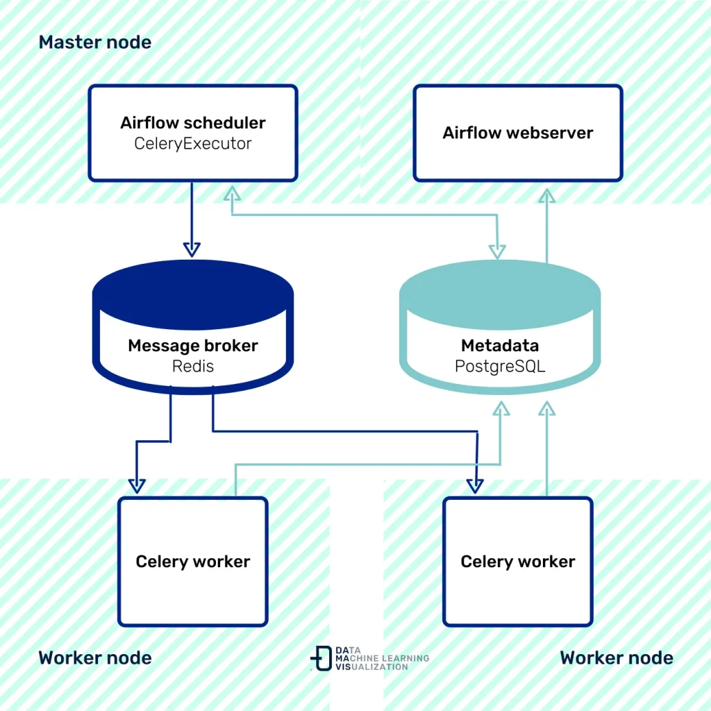
Scalability is a big advantage in this case, as more workers can be added if needed. KubernetesPodOperator gives us the flexibility that each task executed with this operator is deployed in a Kubernetes Pod. Each task will be inside an independent Docker container with all the dependencies and configuration necessary for its execution.
In this way, tasks are independent of the work node on which they are executed.
Airflow will be deployed on a Kubernetes cluster. This allows the process to scale both vertically and horizontally, depending on the needs of the moment.
We will use Helm for deployment, a Kubernetes package manager that allows the configuration, creation and testing of Kubernetes applications.
Now we’ve explained the context, it’s time to get down to work and set up the infrastructure deployment. Let’s get started!
Airflow and Kubernetes implementation guide
In this guide, we assume that:
- You have a running kubernetes cluster (Minikube).
- Helm (v3.4.1) and kubectl (v1.18) are installed.
- You have the source code of the DAGs stored in a Git repository. In case you don’t have a repository, in this link you can find our example repository for the case study.
Creating a namespace in Kubernetes
The application is deployed inside a namespace in Kubernetes:
kubectl create namespace airflowConfiguring the values.yaml file to deploy Airflow
We need to generate a template to display all the elements. Find the example template in the values.yaml file in the Helm repository.
The image we will use will be the official image provided by Apache.
Next, we need to define the following elements:
- Airflow.
- Flower: tool for monitoring the messaging queue.
- Workers: number of workers who take on the workload.
- Redis: messaging queue to transmit the information to the workers.
- PostgreSQL: database that uses Airflow as a backend.
An example of a template is the file airflow-celery.yaml available at this link.
Installing the Helm Chart
To install the chart we will first make sure we have the repository added in Helm:
helm repo add airflow-stable https://airflow-helm.github.io/charts
helm repo update
With this we can now launch the deployment:
helm install airflow --namespace airflow airflow-stable/airflow --values ./airflow-celery.yamlIf the deployment was successful, we should see the following message:
NAME: airflow
LAST DEPLOYED: Fri Jan 29 15:33:06 2021
NAMESPACE: airflow
STATUS: deployed
REVISION: 1
TEST SUITE: None
NOTES:
Congratulations. You have just deployed Apache Airflow

   NOTE: It may take a few minutes for the LoadBalancer IP to be available.
         You can watch the status of the service by running 'kubectl get svc -w airflow'
With the execution of this command we will have the following in the cluster:
- 3 Deployments: Scheduler + web IU + redis + flower.
- 1 Persistent volumes: PostgreSQL.
- 1 Pod per Worker defined.
We can view the status of the services with the following command:
kubectl get service --namespace=airflowNAME TYPE CLUSTER-IP EXTERNAL-IP PORT(S) AGE
airflow-flower ClusterIP 10.107.148.59 <none> 5555/TCP 29m
airflow-postgresql ClusterIP 10.109.52.69 <none> 5432/TCP 29m
airflow-postgresql-headless ClusterIP None <none> 5432/TCP 29m
airflow-redis-headless ClusterIP None <none> 6379/TCP 29m
airflow-redis-master ClusterIP 10.101.106.143 <none> 6379/TCP 29m
airflow-web ClusterIP 10.96.195.146 <none> 8080/TCP 29m
airflow-worker ClusterIP None <none> 8793/TCP 29mkubectl get deployments --namespace airflowNAME READY UP-TO-DATE AVAILABLE AGE
airflow-flower 1/1 1 1 29m
airflow-scheduler 1/1 1 1 29m
airflow-web 1/1 1 1 29mTo access the Airflow service we perform port-forwarding.
kubectl port-forward service/airflow-web 8080:8080 --namespace airflow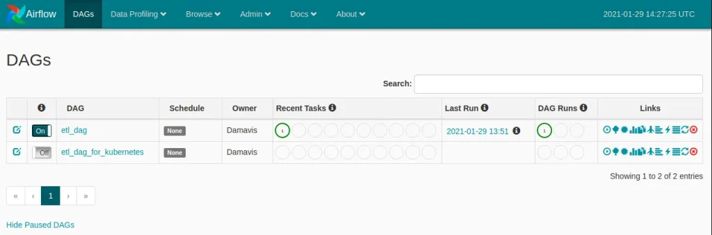
On the other hand, by port-forwarding the Flower service, we can monitor the task queue.
kubectl port-forward service/airflow-flower 5555:5555 --namespace airflow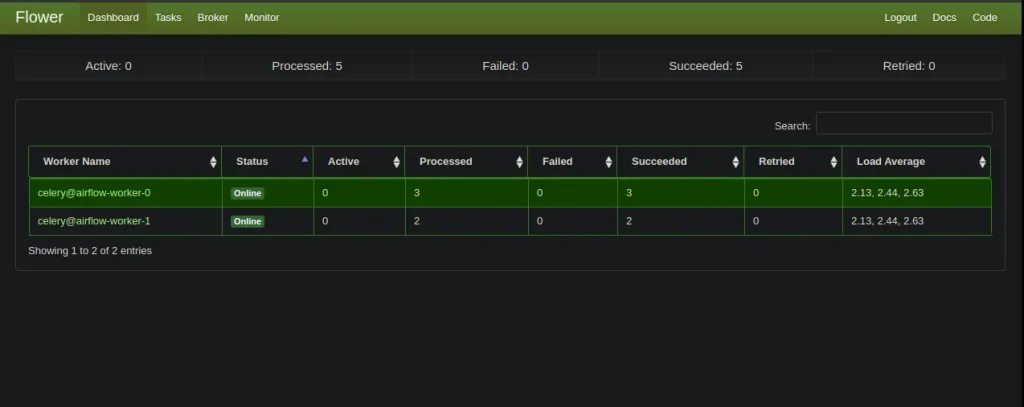
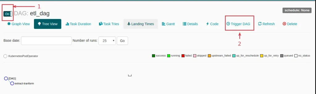
Running a pipeline with KubernetesPodOperator
The file etl_dag_celery.py is a basic example of a DAG with a operation with such operator.
from airflow import DAG
from datetime import datetime, timedelta
from airflow.contrib.operators import kubernetes_pod_operator
default_args = {
'owner': 'Damavis',
'start_date': datetime(2020, 5, 5),
'retries': 1,
'retry_delay': timedelta(seconds=5)
}
with DAG('etl_dag',
default_args=default_args,
schedule_interval=None) as dag:
extract_tranform = kubernetes_pod_operator.KubernetesPodOperator(
namespace='airflow',
image="python:3.7-slim",
cmds=["echo"],
arguments=["This can be the extract part of an ETL"],
labels={"foo": "bar"},
name="extract-tranform",
task_id="extract-tranform",
get_logs=True
)
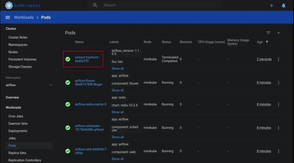
extract_tranformBy running the workflow in Airflow we can see how it works as described above in the dashboard provided by minikube.
And with these steps we have deployed a simple yet versatile Airflow infrastructure with CeleryExecutor on Kubernetes.
This structure allows us to have a first approximation of scalability, although it is limited to the number of workers deployed. The interesting thing would be that this scalability would be determined by the system, and that the network of Pods would be deployed for each task, taking advantage of the power of the Airflow operators, don’t you think?
There is a possibility using KubernetesExecutor, but this will be part of a future post.
Until then, if you found this post useful, you can visit the Data Engineering category of our blog to see more articles like this one and share it with your contacts so they can also read it and give their opinion. See you in networks!
